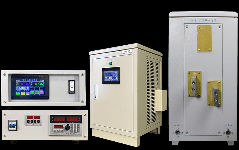
Electroplating rectifier in Electroplating Copper and Tin in PCB Graphic Plating

Selecting Power Size and Control Method for Rectifiers in PCB Copper and Tin Plating Tanks
In the realm of PCB patterned plating, the choice of rectifier power size and control method plays a pivotal role in ensuring efficient and effective plating processes. Let's delve into the considerations and formulas for selecting the appropriate rectifiers for copper and tin plating tanks.
1. Choosing Power Size for Copper Plating Tanks
The size of the plating area is a key factor in determining the power size of the rectifier. Typically, we use the width of the copper plating tank multiplied by the height of the PCB product. For instance, if the width is 30 cm and the height is 6.8 cm, the formula for calculating the rectifier's output current is as follows:
Length×Width×Current Coefficient×100%=Total Output Current of Copper Plating Tank RectifierLength×Width×Current Coefficient×100%=Total Output Current of Copper Plating Tank Rectifier
Using a current coefficient of 2.0 and considering a 100% distribution density, if we apply this formula to our example (30 cm width, 6.8 cm height), the result is 408 amps. Rounding up, we should choose a 450-amp rectifier for copper plating.
2. Determining Power Size for Tin Plating Tanks
Similarly, for tin plating tanks, the formula for calculating the rectifier's output current is:
Width×Current Coefficient×100%=Total Output Current of Tin Plating Tank RectifierWidth×Current Coefficient×100%=Total Output Current of Tin Plating Tank Rectifier
Using a current coefficient of 1.5 and considering a 100% distribution density, if we apply this formula to our example (30 cm width, 6.8 cm height), the result is 306 amps. Rounding up, we should choose a 350-amp rectifier for tin plating.
3. Quantity and Control Method
Since the distribution density differs between the front and back sides of PCB products, each copper and tin plating tank requires two rectifiers. For efficient control and monitoring, we use a communication method like RS-485 to centrally manage and monitor the operation status, set current levels, and receive actual current feedback from each rectifier. A computer is also necessary to record current and voltage data. Therefore, we opt for dual-output rectifiers to ensure equal current distribution to both anode points in the plating tanks, ensuring uniformity in PCB product plating.
In summary, selecting the right power size and control method for rectifiers in PCB patterned plating tanks is crucial for achieving consistent and high-quality plating results. It requires careful consideration of the plating area, current coefficients, distribution density, and efficient control and monitoring systems.

Centralized control Electroplating rectifier