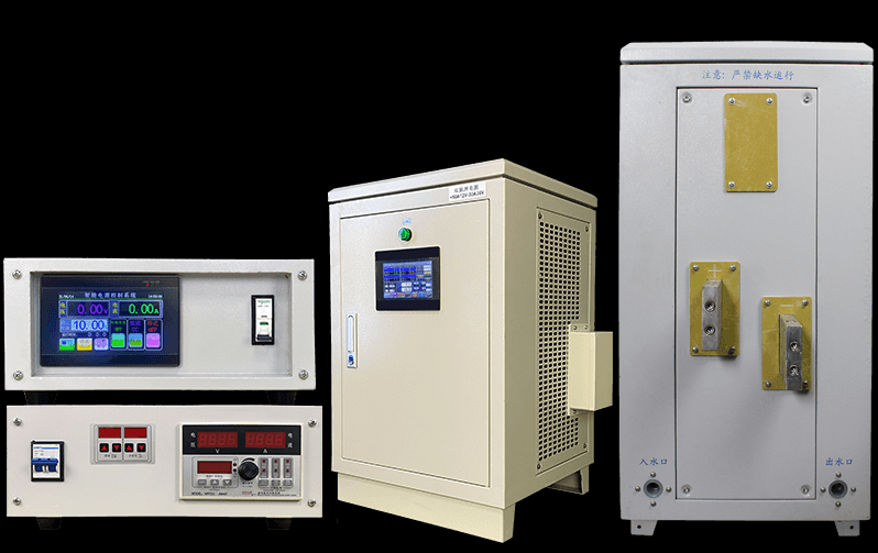
MODBUS RTU Electroplating rectifier

MODBUS RTU Communication protocol
This Communication protocal adopts the standard Modbus protocol ,The transmission mode is RTU (hex).ModBus protocol is a master-slave protocol
The host computer(PLC, HMI,ETC) responds to the Master rectifer as the slave
Communication address :1~32
Function code:reading and writing multiple registers 。
Data format: Via the binary cade transmission。
CRC16: Cyclic redundancy check ,from the address of the slave station on the last byte of the data area , calculates the polynonial code A001(hex)
1 Set of the communication prot
Communication way Asynchronous serial communicaton prot, RS-485。
Baud rate 19200bps
2 Byte data format HEX
. One-bit start bit
. Eight data bits
. One stop bit
. Even parity check
|
1 |
* |
* |
* |
* |
* |
* |
* |
* |
1 |
* |
One-bit start bit data bits(Low-high) stop bit Check
3 Mesage frame format (Define read and write functions from the standpoint of the master station)
Send the Read rectifer register frame
|
Slave address |
Function code |
First register address |
Number of refister |
CRC16 |
|
1byte |
1 byte |
2 byte |
2 byte |
2 byte |
|
1-32 |
03H |
0000H |
0003H |
CrcL, CrcH |
Receive the Read rectifer register frame
|
Slave address |
Function code |
Number of register |
Content of rectifier register data content |
CRC16 |
|
1byte |
1byte |
1byte |
6 byte |
2 byte |
|
1-32 |
03H |
06H |
V, I, ZT |
CrcL, CrcH |
Write the rectifer register farme
|
Slave address |
Function code |
Frist register address |
Number of register |
Numbe of byte |
Content of refister |
CRC16 |
|
1byte |
1byte |
2 bytes |
2 bytes |
1byte |
4 bytes |
2bytes |
|
1-32 |
10H |
000AH |
0002 |
04 |
F,SW |
CrcL, CrcH |
Receive the wirite rectifer register frame
|
Slave address |
Function code |
First register address |
Number of register |
CRC16 |
|
1byte |
1byte |
2bytes |
2bytes |
2bytes |
|
1-32 |
10H |
000AH |
0002 |
CrcL, CrcH |
List of the Function code explain:
|
Function |
ModBus |
Function code |
broadcast |
Number |
|
03H |
Read Holding Registers |
Read the rectifier register |
No |
3 |
|
10H |
Write Multiple Registers |
Write the rectifier register |
No |
2 |
4 Rectifier register list (read register ,wirte register):
|
NO |
Parameter codes |
Name of parameters |
Address |
type |
Rate of Number |
Remark |
|
1 |
V |
Display the value of voltage |
0 |
Read rectfier register |
0-9999 (10hex) |
|
|
2 |
I |
Display the value of current |
1 |
0-9999 (10hex) |
||
|
3 |
ZT |
Dis play the state of rectifer running |
2 |
0-3 (10hex) |
0——without error 1——Overheating 2——overcurrent 3——other error |
|
|
4 |
F |
Set the value of voltate or curent to rectifier |
10 |
Write rectfier register |
0-9999 (10 hex) |
|
|
5 |
SW |
Switching valve |
11 |
(16 hex) |
Check the talbe below for expian this item |
|
Detail of switch bit variable (SW) |
|||||||||||||||||
|
Number of bit |
15 |
14 |
13 |
12 |
11 |
10 |
9 |
8 |
7 |
6 |
5 |
4 |
3 |
2 |
1 |
0 |
|
|
State of “o” (false) |
Off alarm |
D13光耦截止 |
Stop rectifier |
Model of CC |
|||||||||||||
|
Stae of “1” (turth) |
Open alarm |
D13光耦导通 |
Start rectifier |
Model of CV |
|||||||||||||
Memory address table description: 1, all data types are unsigned integer (two bytes).
2. All the data with decimal points in communication transmission are replaced by integers, such as: 1.000 instead of 1000.
(i.e. ignoring the decimal point) 27.9 is replaced by 279.
3, all register data in the transmission process is expressed in hexadecimal numbers, first pass high bytes, then pass low bytes, such as transmission 279, first pass 01H, then pass 23H.
Now let me give you an example, MUDBUSPOLL for MUDBUS485(RUT) communication with our electroplate rectifier.
Connection
The tools used in this example are as follows:
- 1 Laptop (64-bit) with Windows 10 Home Edition operating system.
- Modbuspoll (64-bit) software.(master tool)

USB to RS232 data cable.
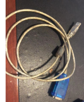
RS232 to RS485 converter

Electroplating rectifier(slave)
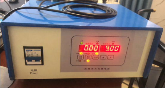
I will test the electroplating rectifier in CV (Constant Voltage) operating mode, setting parameters and examining various details. I will also provide steps and illustrations.
1step:Set the parameters of the communication port.( 19200, 8, E, 1)

2 step : Select MODUS function code (16)
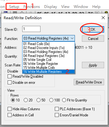
3 step Design the content of the write slave (function code (16)) message.

4 step : set the slave register 10 = hex format ; slave register 11= binary format
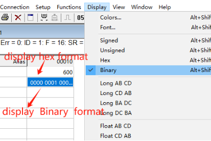
5 step : set register10 value = 400 (4.00 V)

6 step set register 11 value 1 0000 0001

7 step . As a result, the slave set voltage value bit 4.00V, start up, voltage regulation working mode.

//www.linearguider.com/plating-rectifier.html
CGCY Electroplating rectifier
chemical pump